Part 1:
On the cavity side things were much more interesting. After a facing cut similar to the core mold, a pocket was made using first a ⅛” endmill at a depth of .09” and a random spiral pattern. The random spiral added to the cycle time, but created an awesome effect on the part of the beaver face that will be visible to the user. It was a cool way to use the toolpath marks to add to aesthetic. The remachine was done with a 1/32” endmill to create the smaller features between the whiskers, around the eyes, and in the corners of the flares. The 1/32” was run to a depth of .089” to prevent the appearance of toolpath marks on the mold. The outer ring was made with a ¼” ball endmill and the smaller runners from the ring to the face were made with a ⅛” ball


Part 2:
While many of us hoped that our first injection molding runs would result in perfect parts, reality proved to us that optimization is key in trying to reach our nominal values. The following is a summary of the improvements and changes we made to each mold in order to perfect the injection molding and thermoforming processes.
The beaver face was molded using a flat core mold with two small slot shaped pockets to create alignment pins on the face for the future overmolding step and 6 ejector pins located at a radius of .98”.
The cavity mold is a .09” pocket of the beaver face with islands to create the holes in the part for the whiskers and the eyes which will be filled with red plastic during the overmolding process. Additionally, a ¼” ring around the face was machined at the same radius as the ejector pins to serve as an additional runner and allow the face to adhere to the core side of the mold and be ejected more easily.
For the core mold, a simple facing cut was made to remove a thin layer of stock and create a smoother interface between the molds during the IM process. Additionally, a 1/16” endmill was used to create the two small slot shaped pockets. The ejector pin holes were machined using a center drill and a #31 drill.
On the cavity side things were much more interesting. After a facing cut similar to the core mold, a pocket was made using first a ⅛” endmill at a depth of .09” and a random spiral pattern. The random spiral added to the cycle time, but created an awesome effect on the part of the beaver face that will be visible to the user. It was a cool way to use the toolpath marks to add to aesthetic. The remachine was done with a 1/32” endmill to create the smaller features between the whiskers, around the eyes, and in the corners of the flares. The 1/32” was run to a depth of .089” to prevent the appearance of toolpath marks on the mold. The outer ring was made with a ¼” ball endmill and the smaller runners from the ring to the face were made with a ⅛” ball
Beaver Face Core
Step
|
Operation
|
Machine
|
Tool
|
Justification
|
1.
|
Pocket (Standard)
|
PROTOTRAK
|
#3 0.125 ENDMILL1 FLAT- 1/8” DIAMETER 2 FL
|
To save time this will be used to machine the majority of the material at the top of the piece
|
2.
|
Pocket (Remachining)
|
PROTOTRAK
|
#1 0.0625 ENDMILL1 FLAT- 1/16” DIAMETER 2 FL
|
Use this pass to pocket around the eyes and down past the whiskers
|
3.
|
Pocket (Remachining)
|
PROTOTRAK
|
#18 .03125 ENDMILL1 FLAT- 1/32” DIAMETER 2 FL
|
Use this pass to pocket between the whiskers and around the eyes and flames
|
4.
|
Contour (2D)
|
PROTOTRAK
|
#14 .0020 TAPER MILL ENGRAVING TOOL
|
To be used on the edges and corners of the flames to a depth of .04 inches to allow feature to be machined
|
Beaver Face Cavity
Step
|
Operation
|
Machine
|
Tool
|
Justification
|
1.
|
Pocket (Standard)
|
PROTOTRAK
|
#18 .03125 ENDMILL1 FLAT- 1/32” DIAMETER 2 FL
|
Machine the2 alignment pin features on the mold
|
2.
|
Pocket (Remachining)
|
PROTOTRAK
|
#18 .03125 ENDMILL1 FLAT- 1/32” DIAMETER 2 FL
|
Finishing cut on the two alignment pin features
|
4.
|
Core mill center drilling
|
PROTOTRAK
|
Tool #13 0.1875” Center Drill
|
Holes need to be drilled with a mill on the core in order to make the ejector pin holes. This operation creates a center drill hole for the actual drilling operation
|
5.
|
Core mill drilling
|
PROTOTRAK
|
Tool #17 0.1200” Drill
|
Drilling of the ejector pin holes.
|
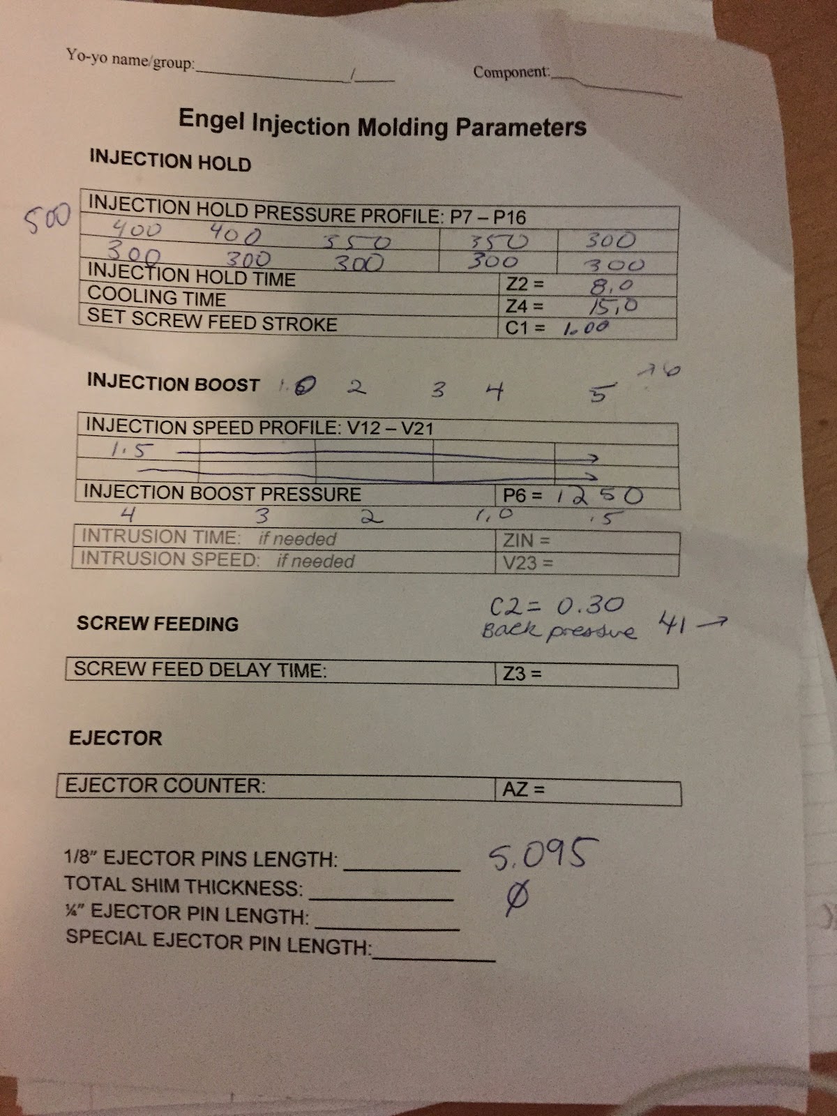
Below is the setup sheet used during Injection Molding on the Dark Colors Engel IM machine. During the first set of testing with the part an Injection boost of 1.5 was used for the entirety of the profile. After analyzing the short shot on the flares of the beaver face, I increased the boost profile to pyramid up and back from 1.0 to 6.0 which allowed the part to be filled completely and reduced some of the knit lines being formed between the beaver whisker holes and the edge of the part.
Injection Speed - 6.3 in/s
Injection Pressure - 58 psi
Packing Time - 8.00 s
Packing Pressure - 41 psi
Shot Size - 21.5 mm
Cooling Time - 15 s
⅛” Ejector pin length - 5.095 in
Total Shim thickness - .0 in
The ejector pin length was shortened to 5.095 to allow some plastic to flow into the holes and help with release after each shot of plastic. The shim thickness was 0 as the molds were machined and measured and did not need any shim compensation.
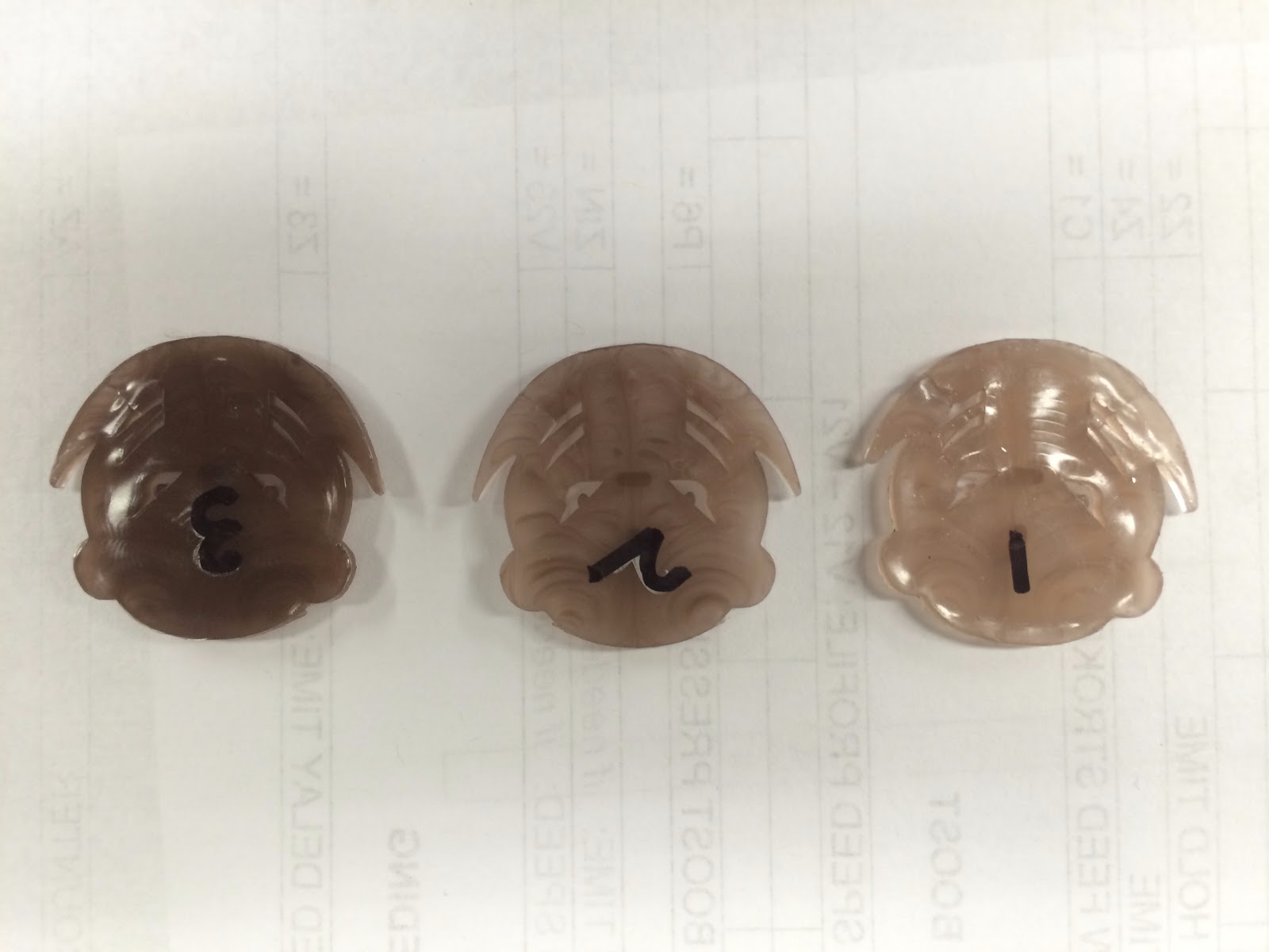
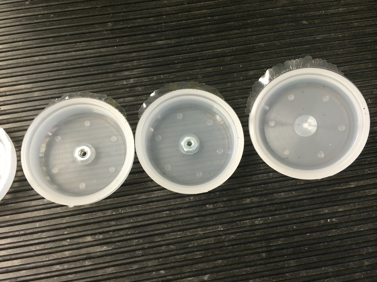
The parts made with the 1.5 injection speed profile and injection hold pressures of 400, 400, 350, 350, 300, 300, 300, 300, 300 are seen below and labelled as part 1. There were several issues with these parts including short shot on the flares, knit lines, and sink marks around the top face. Additionally during the first few runs the mold was being cleaned out by every shot of plastic so the parts gradually became nicer.
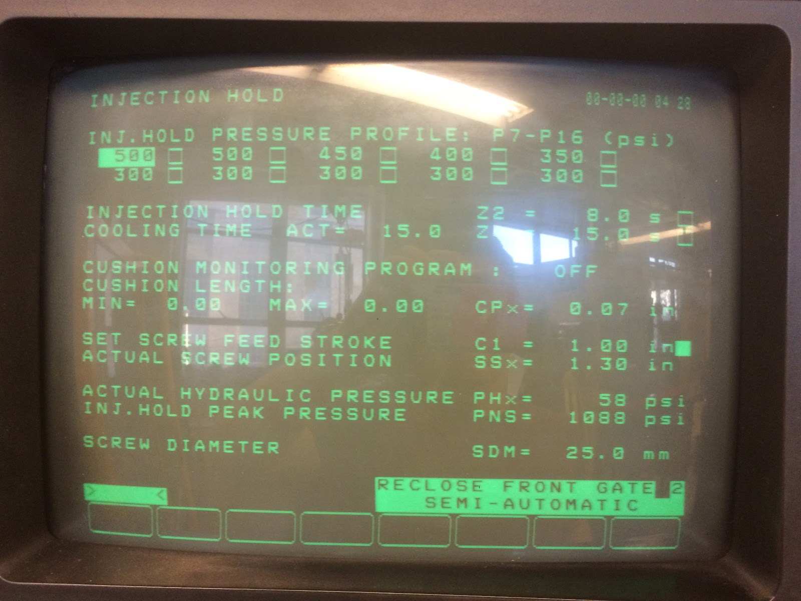
By the last run of test parts the parameters were set to what is seen on the monitors below. By increasing the injection hold pressure and injection boost the knit lines between the holes for the whiskers and the edge of the part decreased significantly. There still needs to be testing done on optimal cooling time as the part may need to be forced to have a different shrinkage depending on the needs of the lid team.
Part 2:
While many of us hoped that our first injection molding runs would result in perfect parts, reality proved to us that optimization is key in trying to reach our nominal values. The following is a summary of the improvements and changes we made to each mold in order to perfect the injection molding and thermoforming processes.
Base Mold:
For the first few
iterations of the base, we were only getting ~3/4 of a part due to a short shot.
So, in order to adjust for
this we increased the shot size from 20mm to 31mm, which fully filled the base.
In order to eliminate some deformities that were appearing, we increased the
cooling time from ~20s to 30s, which is reasonable for a part with this volume.
However, at this larger shot size we began experiencing flash on the edge of
the base close to where the gate is.
In order to deal with this, we experimented with a few parameters. This included adjusting the injection pressure between 60 and 300 psi. The injection pressure did not seem to have a huge effect, although the 60 psi version was a tad bit better after a four or five iterations at each pressure. We also decreased the injection time to 2 seconds, and increased the hold pressure to 50 psi. Overall, we did not experience too many issues with the base as compared to some of our other parts, and the injection molding process for optimization went rather smoothly.
Lid Mold:
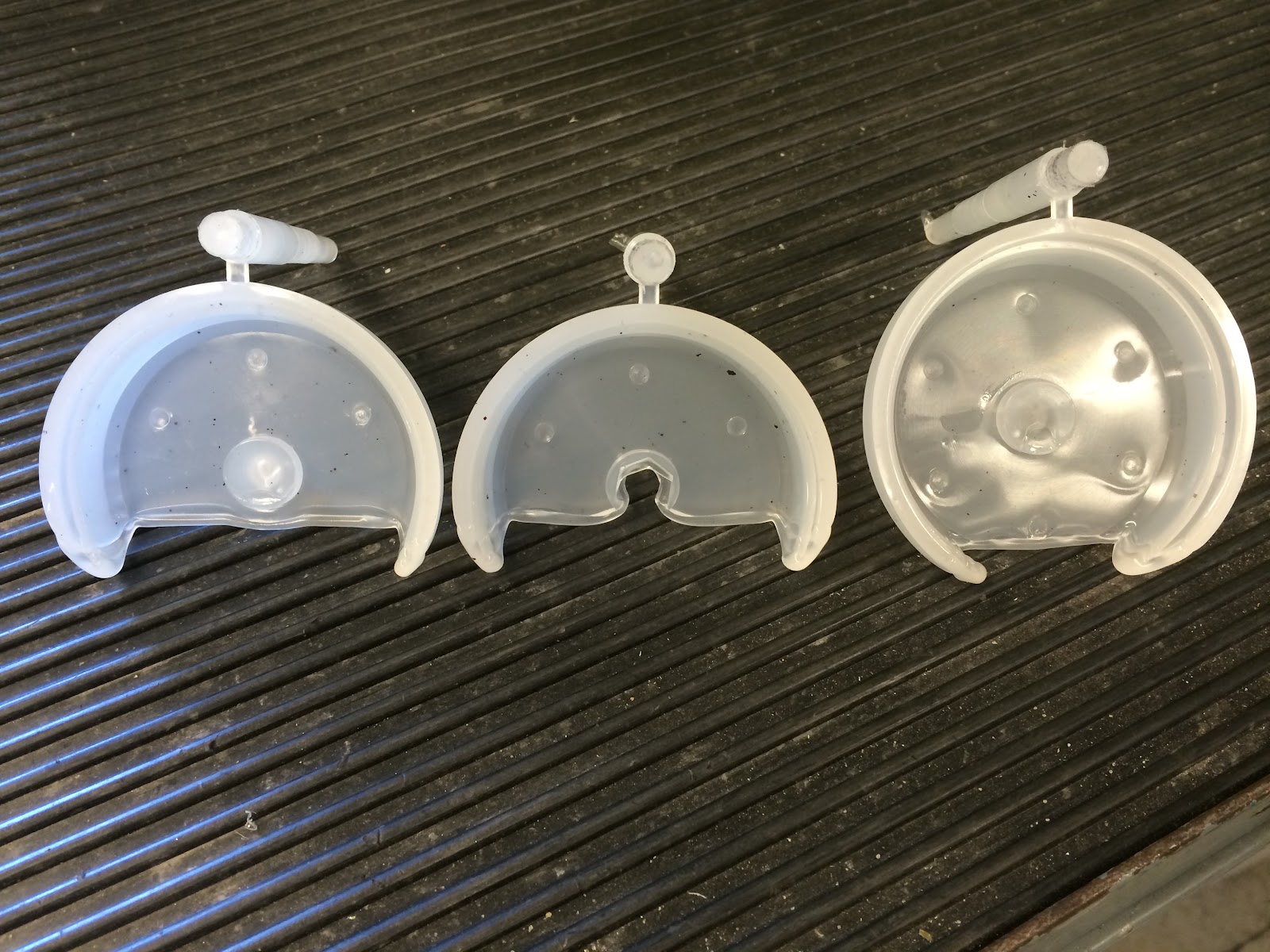
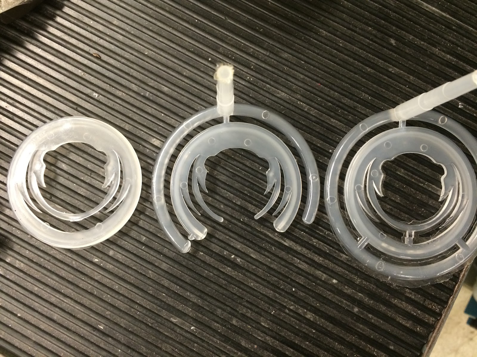
The first challenge that arose with the lid was in creating the molds. Since we wanted to make every corner and edge in our beaver face sharp, this meant that none of the inside corners could be machined as a pocket, as this would give the radius of the tool as the sharpest possible corner. So, instead we created two molds with islands on each one, which fit together exactly. The molds did not interfere with each other at all when the injection molding machine clamped them together, and did not allow any plastic in between the island molds.

Because of the non-symmetric nature of the lid geometry, material was not getting spread throughout the lid evenly, leading to non-uniform shrinkages throughout the part. This caused an overall non-symmetric part, both in outer diameter as well as the cut out central portion, and was a direct cause of the other parts not fitting together with it.
In order to mitigate this, we decided to put a runner around the full outer diameter of the lid, and then add 2 gates (so that now there was a total of 3 gates) in order to more evenly distribute the flow of material to the non-symmetric areas of the part. In addition, in an attempt to minimize the extreme deformity of the thin material separating the beaver face cut out and the splash cut out on the bottom, we added a channel connecting the bottom of the yoyo and this thin layer of material. In the resulting injection molding process, because of the increased volume of material within the lid we had to increase the shot size back up to 21.5mm.
Thermoformed Electronics Tray:
One of the more noticeable problems we faced is that the plastic did not cover the die completely so that the tallest distance of the thermoform was about .307’’(as shown by the sloped curve in the picture). The main cause behind this is because the cooling time was a little too short. Despite this, the sides of the thermoform were able to fit snugly into the base of the yo-yo after cutting off some of the plastic material, which was advantageous to our design.

However, in order to improve the design, we decided to increase the heat time to 430 so that the plastic would stay at a moldable state for a longer period of time. This created the improved results shown below. Notice the decrease of a curve around the supporting pillar.
I really loved reading your thoughts, obviously you know what are you talking about! Your site is so easy to use too, I’ve bookmark it in my folder.
ReplyDeleteinjection molding China