II. Overview

 The Fighting Beaver team collaborated to create
50 yo-yo’s decorated with the MIT Athletics Department fighting beaver logo and
complete with LEDs that cause the toy to light up upon use. The yo-yo is
comprised of a white injection molded base in which a thermoformed electronics
bed rests on the bottom. The white injection molded lid is manufactured with
two openings, one where a black injection molded beaver face snaps in tightly,
and the second for the injection of red plastic in an overmolding procedure.
The lid snaps tightly into a lip in the base to seal the yo-yo for use in a
full assembly. The yo-yo utilizes a .075” string gap for optimal performance.
For aesthetics, vinyl cut stickers of the nose and teeth complete the beaver
face, and a red and black string wraps around the central post.
The Fighting Beaver team collaborated to create
50 yo-yo’s decorated with the MIT Athletics Department fighting beaver logo and
complete with LEDs that cause the toy to light up upon use. The yo-yo is
comprised of a white injection molded base in which a thermoformed electronics
bed rests on the bottom. The white injection molded lid is manufactured with
two openings, one where a black injection molded beaver face snaps in tightly,
and the second for the injection of red plastic in an overmolding procedure.
The lid snaps tightly into a lip in the base to seal the yo-yo for use in a
full assembly. The yo-yo utilizes a .075” string gap for optimal performance.
For aesthetics, vinyl cut stickers of the nose and teeth complete the beaver
face, and a red and black string wraps around the central post.  The yo-yo demonstrates creativity in both the mold design
and the manufacturing process. To create the sharp edges in the holes in the
lid that are signature to the logo but impossible to machine given the tooling
restrictions, the core and cavity molds were machined with islands that matched
on a 5 degree draft. This mold pairing technique allowed the flare around and
below the beaver face to mimic the logo design beautifully.
The yo-yo demonstrates creativity in both the mold design
and the manufacturing process. To create the sharp edges in the holes in the
lid that are signature to the logo but impossible to machine given the tooling
restrictions, the core and cavity molds were machined with islands that matched
on a 5 degree draft. This mold pairing technique allowed the flare around and
below the beaver face to mimic the logo design beautifully.
After analyzing an
assembly of rapid prototyped parts created on the Stratasys Mojo FDM Printer,
the initial three layered snap fit of red, black and white features, was proven
to be too difficult to execute given the sharp corners and small dimensions of
the features, and was quickly iterated to include a white lid, black beaver
face and red overmolded plastic. The overmold utilizes a simple pocketed ring
dimensioned using the average thickness of the snap fit interface on the
production run of lid parts, and a core mold with a forked runner that allows
plastic to enter and flow into the holes in the lid without adhering to its
backside. After overcoming challenges with the initial snap fit of the beaver
and the overmolding design and process, the team is proud to present the final
prototype and analysis of the yo-yo.
Comparison of Designed Specifications to Actual Measured Specifications:
III. Comparison of Designed vs. Measured Specifications
1. Base Snap Fit Inner Diameter
Because we were unsure on what exactly the final dimension of the overmolded
lid snap fit diameter would be, it was difficult to design for a base
dimension. However, we designed for 2.255 inches in the inner diameter,
accounting for a 0.1 inch snap fit interference with what we estimated would be
the final overmolded lid dimension. The produced bases actually averaged 2.265
inches in diameter, which was considerably larger than what was expected. This
can in large part be attributed to human error, in that optimization led to a
25 second cooling time, and the production run was run at a 35 second cooling
time, which caused the base to shrink less than expected. Thus, since the final
snap fit diameters were so close to each other in value, a remake of the base
was necessary. The mold was redesigned so as to make a smaller inner diameter
snap fit on the base. Further, we moved to the Engel injection molding machine
as opposed to the boy, which had the added benefit of eliminating flash on the
parts that was rampant in the parts produced on the boy. The produced bases averaged 2.257 inches in diameter,
which was close to what was originally expected. It is important to note,
however, that in accounting for the uneven diameter dimensions of the overmolded
lid, the base was also uneven in diameter. This way, when snap fitting the lid
into the base, the shorter diameter of the lid was inserted into to the smaller
diameter length of the base (parallel to the plastic flow direction), and the
longer diameter of the lid was inserted into the larger diameter length of the
base (perpendicular to the plastic flow direction). The designed
standard deviation for the base and lids was designed to be 0.00167 inches (the
same as the lid), which would correlate to a 3-sigma tolerance of 0.005 inches.
Given a .015 designed interference, this was reasonable and appropriate, so to
allow for all lids and bases to effectively snap together.
2. Lid snap fit outer diameter:
The measured lid snap fit outer diameter was slightly lower than
its design intention. At first glance of the table, it would appear that the
base inner diameter for the snap fit and the lid outer diameter for the snap
fit were designed to have a 0.1 inch interference in diameter. However, in
reality, they were designed to have a 0.15 inch interference in diameter. This
is because the lid was designed with the expectation that an injection molded
beaver face would be inserted into it, and an overmold process would be
performed on the lid, which would both stretch and compress it. While it was
difficult to predict the exact variations this would cause, it was thought that
these processes would together combine to a net increase of the lid diameter.
The actual results are detailed below under the overmold description. The
designed standard deviation for the lids was designed to be 0.00167 inches (the
same as the base), which would correlate to a 3-sigma tolerance of 0.005
inches. Given a .015 designed interference, this was reasonable and
appropriate, so to allow for all lids and bases to effectively snap together
3. Beaver Face Vertical Diameter:
The beaver face vertical diameter was
larger in its measured dimension of 1.372 in than in its designed 1.370 in. This
increase could be due to the warping of the beaver face during the cooling of
the part causing its vertical dimension to grow while its horizontal shrinks. Additionally
the dimension within the cavity mold could have been slightly large due to the
tool size restriction and the tool paths. The mold was re-machined once to
increase the depth of the part, this adjustment could have potentially
increased the vertical diameter of the beaver face as well.
4.
Overmolded lid resulting
snap fit outer diameter:
Prior to the overmolding process, the black beaver face was
inserted into the lid. This actually caused the lid snap fit dimensions to
become warped, in that the vertical diameter (with reference to the proper
alignment of the beaver face) became elongated significantly while the
horizontal diameter shrunk significantly. This changed the dimensions to about
2.280 in the vertical direction, and 2.260 in the horizontal direction. When
the resulting part underwent the ensuing overmolding process, the overmold
design actually caused the lid to warp in the opposite way, such that the snap
fit on the lid became more circular. While the horizontal and vertical
diameters still differed considerably, the lids were averaged to be 2.270
inches in diameter. Thus, our prediction was correct in that the lid diameter
was elongated in the end, however, the way in which this occurred was quite
different from what was expected.
5. Thermoform Z-axis thickness:
The Z-axis dimension, in the final thermoform run, was
consistently about 0.005” less deep than intended. This is likely due to the
stretching of the thermoplastic, which was not accounted for in the design
calculations. As the melted plastic is pulled over the support towers (the two
hollow towers diametrically opposed, perpendicular to the electronic switches’
line), due to the areal draw ratio of ~3, the thickness of the plastic at the
top of the tower will be reduced, decreasing the overall height. Thermal
contraction may offer some explanation as well, but the part’s cooling time
while still on the mold will have counteracted some of this.
Due to the nature of the design, although this was one of the most
critical dimensions, the error was accommodated for by the compliancy of the
part. Once molded, the bends in the sides of the piece were guillotined off,
leaving a compliant, springy base. This was equal to the inner diameter of the
base at the top of the core, but since the core was drafted fits snugly in when
pressed down inside. This (at reasonable speeds) prevents the electronics bed
from spinning in the yoyo, keeping it balanced. The Z-axis height would
(in the original design) have then pressed flush with the Overmold part when
fitted, thus keeping the electronics further contained.
In the final product, however, the thickness of the Overmold part
had to be adjusted to prevent warpage; this resulted in a less tight push-back
against the thermo part than ideal, but the high compliancy of the part means
that this change was still effectively accommodated.
The internal main cavity diameter of the part was also important,
and in the final production run, fitted the LED board snugly and consistently.
However, not enough clearance was left for the varying dimension of wires, so a
future specification (if accounting for this error) would need to account for
this dimensional change too. The tolerance is not critical, since the wires are
flexible, so a high standard deviation is acceptable (and cheaper).
New Specifications for Yo-yo Mass-Production:

IV. Cost Analysis Summary
The first item in the cost analysis is the cost of prototyping. Plotting total unit cost of additive manufacturing vs. unit cost of 2.008 processes and materials:

We see that for prototyping, additive manufacturing is only more cost efficient for production volumes less than 5 units, which is extremely low.
The 2.008 processes unit cost declines significantly to begin, and levels out at a value of $3.65 per unit as production volume increases to values greater than 10,000.

In high volume production, we see a much more dramatic change in unit costs as a function of production volume.
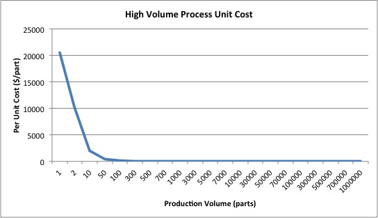
High volume production processes have extremely expensive unit costs for low production volumes, however, drop off significantly and quickly as production volume ramps up. For quantities approaching one million parts, the unit costs decrease to the order of $1.49 per unit. In the high volume production, the electronics are by far the dominant component unit cost, making up 76% of the cost of the yoyo. Aside from this, the remaining material, tooling, and production costs become similar at high volume.
Overall, for the fighting beavers yoyo, additive manufacturing is only valuable for production volumes on the order of 1-5 units produced. High volume production does not become cheaper than the 2.008 processes per unit until production volumes over around 20,000. As parts approach very high production volumes such as one million parts, high volume production becomes significantly cheaper, emphasizing how cost beneficial it can be to produce widgets such as this one on such high scales.
While we do not have access to every manufacturing method and technique available, the available machines in the LMP shop are sufficient to create great alpha products. Our biggest obstacle we had to overcome was the inability to use tools on the CNC mill with radii smaller than 1/32”, thus it was nearly impossible to achieve sharp corners. To solve this problem, we resorted to using many island-island engagements in our mold. Using a five degree draft, our molds had island-island matches to create the flares in the lid, and overmolding was performed on the backside of the lid after the insertion of the beaver face to create the red features. The beaver face mold omitted islands for the nose, teeth and ears, as there was no tool small enough to create the sharp features and an island-island match was not possible. Instead, vinyl decals were applied in the final step of the manufacturing process to keep the features in the prototype.
Thanks and keep sharing such valuable updates through your side.
ReplyDeleteinjection molding China